

Anmelden Kostenlos anmelden


1 / 5
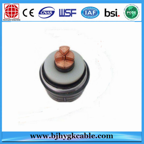
1x1200mm2 110kV CU / XLPE / CAS / MDPE-Stromkabel mit DTS-Faser
| Model No. : | YJLW03 |
|---|---|
| Brand Name : | HUAYUAN YONGTONG |
| Type : | Insulated |
Beijing, Beijing, China
- HändlerGroßhändler
- Hersteller
- OEM -Service
- Plattformzertifizierung

- Video


Produktbeschreibung
Spezifikation:
110 kV XLPE-Kabeldaten
|
Item Nº |
Description |
Unit |
Required Data |
Tenderer/ Contractor Data |
|
|
Manufacturer |
- |
Bidder offers specific |
Beijing Huayuan Cable Co.,Ltd. |
|
|
Manufacturer reference/designation |
- |
- |
IEC 60840 |
|
|
Manufacturing and test standards in accordance with IEC and section 2 of this document. |
- |
Yes |
YES |
|
2.1 |
Insulation strength |
|
|
|
|
|
Nominal operating voltage, phase to earth, Uo |
kV |
64 |
64 |
|
|
Nominal operating voltage, phase to phase |
kV |
110 |
110 |
|
|
Maximum operating voltage, phase to phase, U,n |
kV |
123 |
123 |
|
|
Lightning impulse withstand voltage (peak) |
kV |
550 |
550 |
|
|
Power frequency withstand voltage |
kV |
230 |
160 |
|
2.2 |
Conductor |
|
|
|
|
|
Material |
- |
copper |
copper |
|
|
Nominal cross-section |
mm2 |
1200 |
1200 |
|
|
Shape |
- |
Milliken(strandedandsegmented) |
Milliken(stranded and segmented) |
|
|
Nominal diameter |
mm |
|
|
|
|
Number of segments |
- |
four, five or six |
five |
|
2.3 |
Conductor screen ( inner shielding layer) |
|
|
|
|
|
Material |
- |
|
wrapping semi-cond.tapes +extruded semi-cond. XLPE compound |
|
|
Visible irregularities on outer surface |
µm |
≤ 60 |
≤ 80 |
|
|
Production method
|
|
Extrusion semi-Conducting surrounding |
Extrusion semi-Conducting |
|
|
Resistivity |
Ohm.m |
≤ 1000 |
≤ 1000 |
|
|
Wall thickness |
|
|
|
|
|
• average value |
mm |
0.8 |
≥1.2 |
|
|
• min value |
mm |
80% of average value |
1.0 |
|
|
Nominal outer diameter |
mm |
|
46.1 |
|
2.4 |
Insulation |
|
|
|
|
|
Material |
|
XLPE |
XLPE |
|
|
Maximum dielectric stress at conductor screen |
kV/mm |
10.5 |
10.5 |
|
|
Maximum dielectric stress at insulation screen |
kV/mm |
5.5 |
5.5 |
|
|
inner diameter of insulator |
mm |
|
46.1(nominal) |
|
|
external diameter of insulator |
mm |
|
78.1(nominal) |
|
|
maximum thickness |
mm |
16 |
16.8 |
|
|
Min tensile strength (without aging) |
N/mm2 |
12.5 |
12.5 |
|
|
Minimum wall thickness
|
-
|
> 90% of average |
14.4mm |
|
|
Maximum wall thickness
|
|
(tmax-tmin)/tmax ≤ 0.15 |
(tmax-tmin)/tmax ≤ 0.15 |
|
|
Max. visible irregularities |
µm |
≤ 50 |
≤ 80 |
|
|
Max. partial discharge |
pC |
≤ 5 |
≤ 5 |
|
|
Thermal resistivity according to IEC 287 |
K.m/W |
|
3.5 |
|
|
Max losses/tan delta |
- |
|
0.001 |
|
|
Electrical field stress |
|
|
|
|
|
• Inner shielding layer |
kV/mm |
≤ 10.5 |
5.27 |
|
|
• Outer shielding layer |
kV/mm |
≤ 5.5 |
3.11 |
|
|
Min tensile strength |
N/mm2 |
12.5 |
12.5 |
|
|
Nominal outer diameter |
mm |
|
78.1 |
|
2.5 |
Insulation screen ( outer shielding layer ) |
|
|
|
|
|
Average wall thickness |
mm |
> 0.8 |
> 0.8 |
|
|
Resistivity |
Ohm.m |
≤ 500 |
≤ 500 |
|
|
Visible irregularities |
mm |
≤ 80 |
≤ 80 |
|
|
Difference between max and min diameter |
mm |
≤ 1.2 |
≤3.0 |
|
|
Nominal outer diameter |
mm |
|
80.1 |
|
2.7 |
Longitudinal water-sealing swell layer |
|
|
|
|
|
• Swelling powder |
- |
Yes |
NO |
|
|
• Swelling tape |
- |
Yes |
Yes |
|
|
• Water tightness ( pressure withstand) |
-
|
≥ 1m water Level |
≥ 1m water Level |
|
|
Nominal outer diameter |
mm |
|
86.1 |
|
2.8 |
Metal Sheath |
|
|
|
|
|
Short circuit capability (1 sec) |
KA |
40 |
≥40 |
|
|
Type |
- |
|
|
|
|
Aluminium laminated sheath |
|
|
|
|
|
• construction method |
- |
|
NA |
|
|
• Material/composition of material |
- |
|
NA |
|
|
• Nominal cross section of sheath |
mm2 |
|
NA |
|
|
• Wall thickness |
mm |
|
NA |
|
|
• Average thickness |
mm |
|
NA |
|
|
or |
|
|
|
|
|
corrugated aluminium sheath |
|
|
|
|
|
• construction method |
- |
Annular ringtype |
Annular ring type |
|
|
• Material/composition of material |
|
|
Welding corrugated aluminium sheath |
|
|
• Nominal cross section of sheath |
mm2 |
|
785 |
|
|
• Wall thickness |
mm |
|
2.4(nominal) |
|
|
• Average thickness |
mm |
|
≥2.1 |
|
|
Nominal outer diameter |
mm |
|
112.0 |
|
2.9 |
Corrosion proof coating |
|
|
|
|
|
Material |
- |
Bitumen |
Bitumen |
|
|
Wall thickness |
mm |
|
0.25 |
|
|
Nominal outer diameter |
mm |
|
112.5 |
|
2.10 |
Outer sheath ( protective layer) |
|
|
|
|
|
Material |
|
PE |
MDPE |
|
|
Max/min wall thickness |
mm |
|
5.8/4.1 |
|
|
Nominal wall thickness |
mm |
< 4.5 |
5.0 |
|
|
Thermal resistivity |
K.m/W |
|
3.6 |
|
|
Maximum permissible temperature |
°C |
|
|
|
|
(1) normal continuous operation |
°C |
|
90 |
|
|
(2) emergency (short time) operation |
°C |
|
105 |
|
|
(3) short circuit (very short time) |
°C |
|
250(not exceed 5s) |
|
|
Colour |
- |
Black |
Black |
|
|
Tensile strength without aging |
N/mm2 |
10 |
10 |
|
|
Nominal outer diameter |
mm |
|
122.5 |
|
2.11 |
Transmission capacity |
|
|
|
|
|
one cable circuit in operation |
MVA |
202 |
202 |
|
|
two cable circuits in operation(*) |
MVA |
2 x 166 |
2 x 166 |
|
|
(*) Bidder shall state the maximum transmission capacity when two cable circuit in operation |
|
|
|
|
2.12 |
Reactive power requirements |
|
|
|
|
|
Maximum charging current |
A/km |
12 |
12 |
|
2.13 |
Short circuit currents |
|
|
|
|
|
Three phase fault current, 1 sec |
kA |
≥ 40 |
≥ 40 |
|
|
Single phase fault current, 1 sec |
kA |
≥ 40 |
≥ 40 |
|
|
Permissible short circuit currents of cable ( pre-fault conditions: max permissible conductor temperature ) |
|
|
|
|
|
(1) for conductor (three phase fault current, 1 sec) |
kA |
|
172 |
|
|
(2) for screen / metal sheath (single phase fault current, 0.5 sec) |
kA |
|
101 |
|
|
(3) for screen / metal sheath (single phase fault current, 1 sec) |
kA |
|
73 |
|
|
(4) for screen / metal sheath (single phase fault current, 3 sec) |
kA |
|
44 |
|
|
Max conductor temperature for three phase/earth fault |
°C |
250 |
250(not exceed 5s) |
|
2.14 |
Electrical Parameters |
|
|
|
|
|
Copper purity |
- |
99.99% |
99.99% |
|
|
Nominal resistance |
Ohm/km |
|
|
|
|
DC resistance of conductor at 20 °C (R0) |
Ohm/km |
0.0151 |
|
|
|
DC resistance of conductor at 90 °C (R`) |
Ohm/km |
|
≤0.0193 |
|
|
AC resistance of conductor at 90 °C (R) |
Ohm/km |
|
≤0.0201 |
|
|
DC resistance of conductor of metal sheath at 20 °C |
Ohm/km |
|
≤0.0396(Al sheath) |
|
|
DC resistance of conductor of copper wire screen at 20 °C |
Ohm/km |
|
NA |
|
|
AC resistance of conductor at Thermal of conductor at demand current (915A) (RIyc) |
Ohm/km |
|
0.0201 |
|
|
Max field strength at conductor screen at U0=64 kV |
kV/mm |
|
10.5 |
|
|
Charging current per phase at operating voltage |
A/km |
|
12 |
|
|
Charging power per circuit at operating voltage |
kVar/km |
|
1320 |
|
|
Dielectric loss factor at 20/90 °C |
p.u. |
|
0.001/0.001 |
|
|
Inductance for flat formation (275 mm between phases) |
|
|
|
|
|
Phase A1 |
mH/km |
|
0.637 |
|
|
Phase B1 |
mH/km |
|
0.430 |
|
|
Phase C1 |
mH/km |
|
0.637 |
|
|
Reactance for flat formation (275 mm between phases) |
|
|
|
|
|
Phase A1 |
Ohm/km |
|
0.201 |
|
|
Phase B1 |
Ohm/km |
|
0.135 |
|
|
Phase C1 |
Ohm/km |
|
0.201 |
|
|
Surge impedance of cable |
Ohm |
|
38.7 |
|
|
Max positive sequence & negative sequence impedance |
|
|
|
|
|
(1) with sheath current |
Ohm/km |
|
0.0616+j0.0249 (flat formation) |
|
|
(2) without sheath current |
Ohm/km |
|
0.0201+j0.153 (flat formation) |
|
|
Max zero sequence impedance (return currents in sheath) |
Ohm/km |
|
0.168+j1.654 (flat formation) |
|
|
Temperature of conductor at demand current (θIyc) |
°C |
|
90 |
|
|
External diameter of conductor (dc) |
mm |
|
42.1(nominal) |
|
|
Diameter over insulation (Di) |
mm |
|
78.1(nominal) |
|
|
Insulation thickness (ti) |
mm |
|
16.0(nominal) |
|
|
Inner diameter of insulation (Di - ti) |
mm |
|
46.1(nominal) |
|
|
Loss factor of insulation (tan δ) |
|
|
0.001(max.) |
|
|
External diameter of metal sheath (Ds) |
mm |
|
112.0(nominal) |
|
|
Thickness of the sheath (t s ) |
mm |
|
2.4(nominal) |
|
|
Mean diameter of sheath or screen (d) |
mm |
|
104.1 |
|
|
a.c. resistance of cable sheath or screen (Rs) |
Ohm/km |
|
0.049(at 65℃) |
|
|
Sheath resistivity at 200C (ρs) |
Ohm.km |
|
2.83 ×10⁻⁵ |
|
|
Reactance of sheath (X1) |
Ohm/km |
|
0.130 |
|
|
Ratio of the losses in the sheath and amour (if any). (λ1) |
|
|
0.167 flat formation) |
|
|
Ratio of the losses in the sheath and amour (if any) at operating current specified in bidding document. (λ1yc) |
|
|
0.167(flat formation) |
|
|
Ratio of the losses in one sheath caused by circulating currents in the sheath to losses in one conductor (λ1`) |
|
|
0(flat formation, cross connected) |
|
|
Ratio of the losses in one sheath caused by eddy currents to the losses in one conductor (λ1"). |
|
|
0.167(flat formation) |
|
2.15 |
Current ratings |
|
|
|
|
|
Max permissible continuous current carrying capacity per circuit with cross-bonding, laid in HDPE pipes 225 mm diameter, buried (operation of one circuit) |
A |
1059 |
1059(1circuit,phase spacing 275, flat formation, cross connected , depth of laying 3100 mm ,thermal resistivity of soil 1.0 k.m/W,30℃,in pipe,pipe outer diameter 225mm) |
|
|
Max permissible continuous current carrying capacity per circuit with cross-bonding, laid in HDPE pipes 225 mm diameter, buried (operation of two circuits) |
A |
871 |
871(2circuit,phase spacing 275, flat formation, cross connected , depth of laying 3100 mm ,thermal resistivity of soil 1.0 k.m/W,30℃,in pipe,pipe outer diameter 225mm) |
|
|
Max conductor temperature at rated current |
°C |
|
90 |
|
|
Max continuous conductor temperature |
°C |
90 |
90 |
|
|
Max permissible transmission capacity at operating voltage for |
|
|
|
|
|
(1) one circuit in operation |
MVA |
|
202 |
|
|
(2) two circuits in operation |
MVA |
|
2 x 166 |
|
|
Rated minimum continuous current per circuit (operation of one circuit) |
A |
|
1059(1circuit,phase spacing 275, flat formation, cross connected , depth of laying 3100 mm ,thermal resistivity of soil 1.0 k.m/W,30℃ in pipe, pipe outer diameter 225mm) |
|
|
Rated minimum continuous current per circuit (operation of both circuit) |
A |
|
871(2circuit,phase spacing 275, flat formation, cross connected , depth of laying 3100 mm ,thermal resistivity of soil 1.0 k.m/W,30℃ in pipe ,pipe outer diameter 225mm) |
|
|
System load factor |
- |
0.8 |
0.8 |
|
2.16 |
Cable losses |
|
|
|
|
|
Max continuous current, cross-bonding, nominal voltage, 40 °C |
|
|
|
|
|
(1) conductor |
kW/km |
Bidder offers specific |
22.54(I=1059A,per phase) |
|
|
(2) dielectric |
kW/km |
Bidder offers specific |
0.33(per phase) |
|
|
(3) metal screen |
kW/km |
Bidder offers specific |
NA |
|
|
(4) metal sheath |
kW/km |
Bidder offers specific |
3.76(I=1059A,per phase) |
|
|
(5) total losses at rated capacity (total of 1,2,3 and 4 ) |
kW/km |
Bidder offers specific |
26.63(per phase) |
|
2.17 |
Mechanical data and dimension of cable |
|
|
|
|
|
Outer diameter (De) |
mm |
|
122.5(nominal) |
|
|
Net weight |
Kg/km |
|
18100(approx.) |
|
|
Max delivery length (according site conditions) |
m |
|
1000 |
|
|
Min permissible bending radius (according site conditions) |
m |
|
2.45 |
|
|
Max permitted pulling tension |
kN |
|
84(of conductor) |
|
2.18 |
Longevity of cable |
years |
> 30 |
> 30 |
|
2.19 |
Minimum bending radius |
|
|
|
|
|
- at laying (R1) |
|
R1=20*(d+D)*1.05 R2=1.5R1 d: conductor diameter D: outer cable diameter |
R1=20*(d+D)*1.05 R2=1.5R1 d: conductor diameter D: outer cable diameter
|
Leiterstruktur

CU / XLPE / CAS / MDPE 64 / 110kV 1x1200 mm2
|
Structure |
Nominal Thickness(mm) |
Nominal Diameter(mm) |
|
1 Five(5) segmental copper conductor |
/ |
42.1± 0.6 |
|
2 Semi-conductor tape |
0.14 |
43.1 |
|
3 Conductor screen (wrapped +extrusion) |
2.0 |
46.1 |
|
4 XLPE Insulation |
16.0 |
78.1±1.5 |
|
5 Insulation screen |
1.0 |
80.1±1.5 |
|
6 Semi-conductor water blocking tape |
2.0 |
86.1 |
|
7. Fiber optic cable |
One root 2 core multimode 50/125μm round armored fiber optic cable |
|
|
8 Corrugated aluminium sheath(welding) |
2.4 |
112.0 |
|
9 Anti corrosion layer (Bitumen) |
0.25 |
112.5 |
|
10 MDPE Outer sheath |
5.0 |
122.5 |
|
11 Semi-cond. Coating(Graphite) |
|
122.5±3.0 |

Werkstatt

Paket


Lieferung und Zahlung


Ehre

Kunde

1. Kern-Kupferleiter 2. Dreikern-Kupferleiter 3. Niedrig Rauch-Halogen-freies Kabel 4. Halogenfreies Kabel 5. Niedrig Rauchkabel 6. Null-Halogen-Kabel


Beijing, Beijing, China
- HändlerGroßhändler
- Hersteller
- OEM -Service
- Plattformzertifizierung
- Video
Senden Sie Ihre Anfrage an diesen Lieferanten